
High pressure flanges

Robust flange connections for hydraulic systems.

Explore SAE flanges, split flange halves, pump flanges and related components for high-pressure and large-bore applications. Suitable for mobile hydraulics, machinery and industrial systems.

SAE flanges for hydraulic systems

Robust flange connections for high pressures, large bore sizes and reliable installation in hydraulic systems.

SAE flanges are used to connect hydraulic pipes, hoses, pumps, motors, cylinders and other components safely. A flange head, split flange halves, bolts and an O-ring form a strong, detachable connection suitable for high pressures and high flow rates.

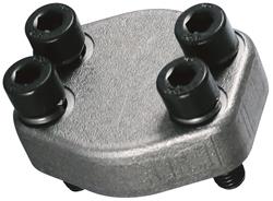
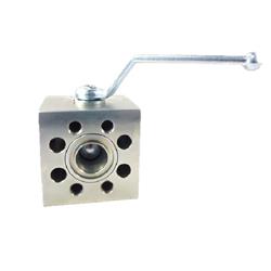
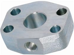
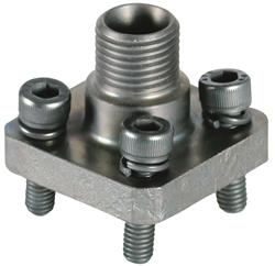
Leeuwtechniek supplies SAE flanges and related components for a wide range of hydraulic applications. The range includes threaded flanges, socket-weld flanges, pump flanges, blanking flanges, adapter flanges, split flange halves, flange-to-tube adapters, seals, bolts and elbow and tee blocks.

Designed for demanding applications

SAE flange connections are designed for hydraulic systems with high pressures, large bore sizes and heavy mechanical loads.

Detachable and easy to maintain

A flange connection can be disconnected for maintenance, inspection or component replacement.

Where are SAE flanges used?

  • Hydraulic pumps
  • Hydraulic motors
  • Mobile hydraulic systems
  • Earthmoving machinery
  • Agricultural machinery
  • Machinery and equipment manufacturing
  • Industrial systems
  • Shipbuilding and offshore applications
  • Transport equipment and vehicle manufacturing
  • Heavy-duty process installations

SAE flanges are particularly useful when threaded connections do not provide sufficient flow capacity or when the mechanical load and system pressure require a more robust connection.

Types of SAE flange

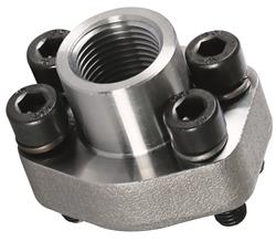
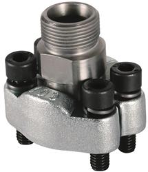
Threaded flanges

Combine an SAE flange connection with a female or male thread for connection to other components.

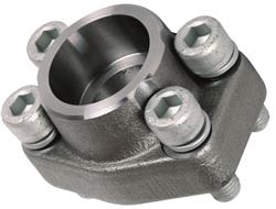
Socket-weld flanges

Are permanently welded to a hydraulic tube or pipe to create a strong transition to an SAE flange connection.

Pump flanges

Designed for connection to hydraulic pumps, motors and other components with an SAE flange port.

Blanking flanges

Safely seal unused flange ports during operation, maintenance or temporary storage.

Adapter flanges

Are installed between components to add connections, measuring points or other functions.

Flange-to-tube adapters

Provide a transition from an SAE flange to a hydraulic tube with a 24-degree cutting-ring connection.

Split flange halves

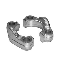
Use bolts to clamp the flange head against the flange port and provide mechanical retention.

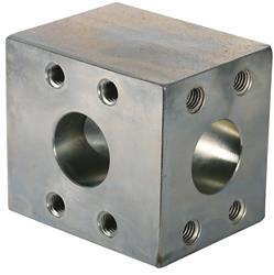
Elbow and tee blocks

Change or divide the direction of flow within a hydraulic flange system.

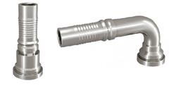
SAE flange hose fittings

Connect hydraulic hoses directly to an SAE flange port.

Code 61 and Code 62

SAE flanges are commonly divided into Code 61 and Code 62. These are also frequently referred to as the 3,000 psi and 6,000 psi series. The two versions differ in pressure class, bolt pattern, flange thickness and typical application. Components from the two series are not automatically interchangeable.

Series Characteristic Typical application
3,000 psi Standard-pressure series General hydraulic systems and medium-pressure applications
6,000 psi Heavier-duty high-pressure series Heavy-duty hydraulic systems and higher system pressures

Always check the product specifications and dimensions. The permissible working pressure depends not only on the series, but also on the size, material, temperature and manufacturer.

How an SAE flange connection works

An SAE flange connection normally consists of a flange head, two split flange halves, four bolts and an O-ring. The O-ring sits in a groove and seals against the flat face of the flange port.

The bolts and split flange halves press the flange head against the port. This creates a mechanically strong connection, while the O-ring provides the fluid-tight seal.

Seals and O-rings

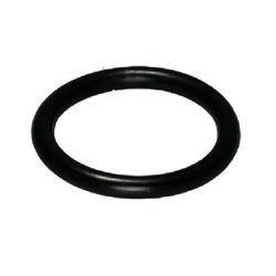
The O-ring is an essential part of the flange connection. Its dimensions and material must be compatible with the flange size, fluid and operating temperature.

  • Check the correct O-ring size
  • Use a suitable sealing material
  • Inspect the groove for damage
  • Make sure the O-ring is not twisted
  • Lubricate only when specified
  • Replace damaged O-rings

An incorrect or damaged O-ring can cause leakage even when the flange components have been assembled correctly.

Materials

Steel

Widely used for its high strength and suitability for heavy-duty hydraulic applications.

Stainless steel

Suitable for corrosive, wet and chemically demanding environments.

Surface-treated steel

Provided with a protective coating to limit corrosion during use and storage.

Standards and dimensions

SAE flange connections use standardised dimensions. Important factors include the bolt pattern, centre-to-centre distance, flange diameter, O-ring groove and pressure series.

  • SAE J518
  • ISO 6162
  • Code 61 / 3,000 psi series
  • Code 62 / 6,000 psi series
  • Standardised bolt patterns
  • Product-specific pressure ratings

Installing SAE flanges

Thoroughly clean the flange faces, O-ring groove and bolt holes. Fit an undamaged O-ring in the groove and make sure it is not twisted or pinched.

Fit the split flange halves and tighten the bolts evenly in a diagonal sequence. This draws the flange squarely against the port and loads the O-ring evenly. Use the specified tightening torque and suitable tools.

Inspection and maintenance

  • Check for leakage
  • Inspect bolts for loosening
  • Check split flange halves for cracks
  • Look for signs of corrosion
  • Inspect the O-ring and groove after disassembly
  • Replace damaged components promptly

An SAE flange connection requires little maintenance, but it should be inspected after maintenance work, pressure peaks, severe vibration or visible leakage.

Frequently asked questions about SAE flanges

What is the difference between Code 61 and Code 62?

Code 61 is the standard-pressure series and is commonly referred to as the 3,000 psi series. Code 62, commonly referred to as the 6,000 psi series, has a heavier design for higher pressures. Dimensions and bolt patterns may differ.

Can I combine 3,000 psi and 6,000 psi components?

No. Only use components designed for the same series and nominal size.

Which O-ring do I need?

The correct O-ring is determined by the flange size, groove dimensions, fluid and operating temperature.

Why is an SAE flange leaking?

Possible causes include a damaged O-ring, contaminated flange faces, unevenly tightened bolts or an incorrect combination of components.

Should the bolts be tightened in a diagonal sequence?

Yes. Tightening the bolts in a diagonal sequence helps draw the flange evenly against the port.

Can an SAE flange be reassembled?

Yes, provided that all components are undamaged. Replace the O-ring if there is any doubt or when required by the manufacturer.

Order SAE flanges from Leeuwtechniek

Leeuwtechniek supplies SAE flanges, threaded flanges, socket-weld flanges, pump flanges, blanking flanges, adapter flanges, split flange halves, bolts, O-rings and connection blocks for hydraulic systems.

Always consult the technical product data. If you are unsure about the series, size, pressure class, O-ring, bolt pattern or connection type, Leeuwtechniek can help you select the right flange connection.